
Preview and Confirm Solutions
- Click Next to preview and confirm the solution.
- Select a device solution and model. You can do the following as required.

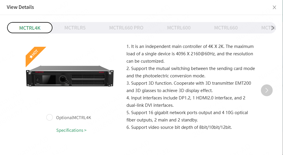
- Change Model: For devices and receiving cards, hover the mouse over the corresponding section, click Change Model, and select a model to replace the current one from the View Details window that appears.
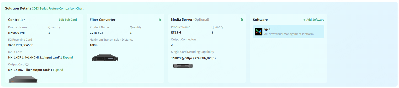
If 5G Transmission is selected in the advanced configuration, the supported controller and 5G receiving card information will be displayed.
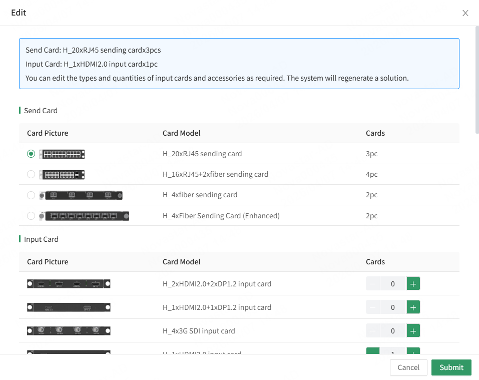
- Edit Sub Card: Click Edit Sub Card to edit the cards for devices containing cards.
You can select input and output cards and specify their quantities.
For the H/E+MCTRL splicing control solutions, you can also select an output card to work with the controller (the available output cards depend on the capabilities of the controller). Once the cards are selected, click Submit.
- Edit Media Server: For a media server, click
 to edit the output connector quantity and click the drop-down list to change the graphics processing card.
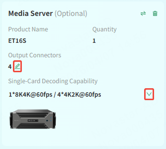
Note: Modifying the output connector quantity on the media server does not affect the number of controllers.
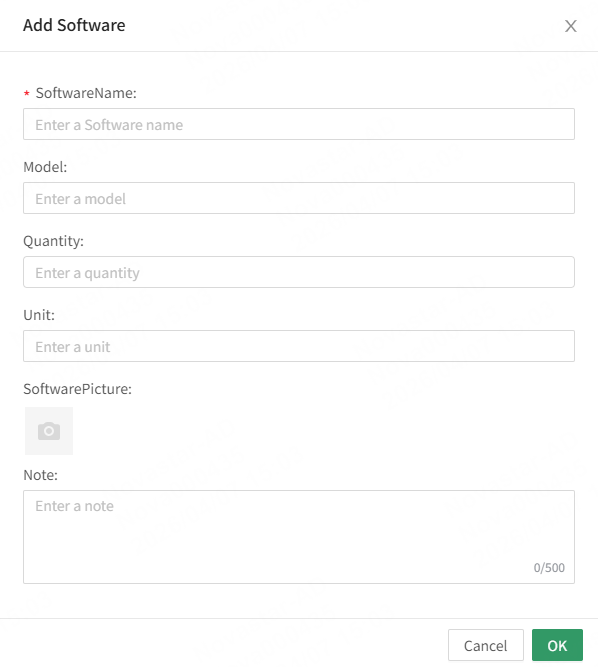
- Add Software: Click Add Software, and add the relevant software in the window that appears according to the project's actual needs, such as VMP or NovaLCT, then click OK.
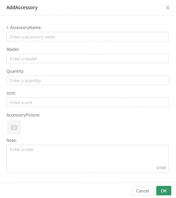
- In the Accessories section, click Add Accessory, and add related accessories in the window that appears according to the project's actual needs, such as light sensors, fiber converters, or multifunction cards, then click OK.
- View the receiving card connection. You can select a receiving card connection method (
 ,
,  ), click
  to view the diagram in full screen, or click Download Connection Diagram to download the diagram.
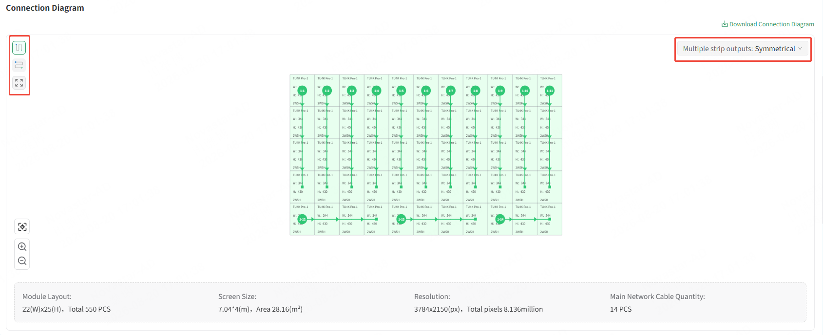
Note: If the unit type of the screen is set to Module, you can also click the drop-down list to select the connection method for the receiving cards to load models (multiple strip outputs), including Standard, Symmetrical, Triple, Quadruple, Pentuple, and Sextuple.
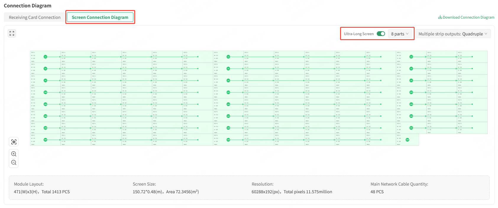
For an ultra-long screen, you can view the Screen Connection Diagram. The ultra-long screen is enabled by default and can be disabled as needed (Note: To disable it, the preceding configuration parameters must meet the requirements for a non-ultra-long screen solution).
For an ultra-long screen, you can select the number of parts, ranging from 2 parts to 8 parts (the selected number of parts must be compatible with the current solution). The Receiving Card Connection and Screen Connection Diagram will update in real time based on the selected number of parts.
- View the device connection.
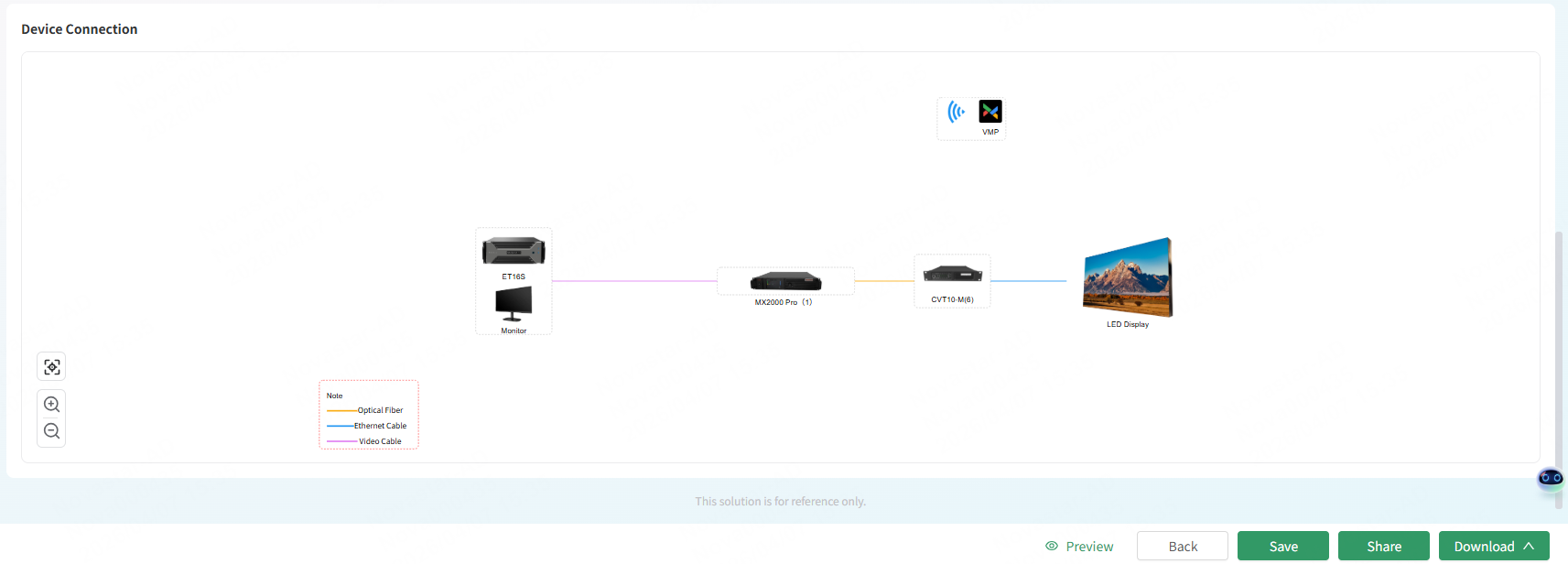
- After the solution configuration is done, do the following as required.
- Preview: Click Preview to preview the configured solution.
- Back: If you want to change the information on the previous page, click Back to go back to the previous page.
- Save: Click Save to save the solution to the solution list.
- Share: Click Share to share the solution with others
- Download: Click Download and select Solution Package, Solution Overview, Cable Routing Diagram, Screen Connection Diagram (available for ultra-long screens only),or Material List EXCEL.
- (Optional) Go to the solution list to manage the saved solutions.

- (Optional) From the solution list, do the following as needed.
- Click a solution to go to the detailed information page to view the solution details. You can also click Share, Download, or Edit at the top right of the page to share, download or edit the solution.
- Click Share in the Action column to share the solution with others via a link.
- Click Download in the Action column and select Solution Package, Solution Overview, Cable Routing Diagram, or Material List EXCEL.
- Click Edit in the Action column to edit the solution.
- Click More and select Copy, Rename, or Delete to generate a copy of the current solution, rename or delete the current solution.